This project was started after watching this youtube video by curiousmarc, where he and Ken Shirriff repair a broken PET2001.
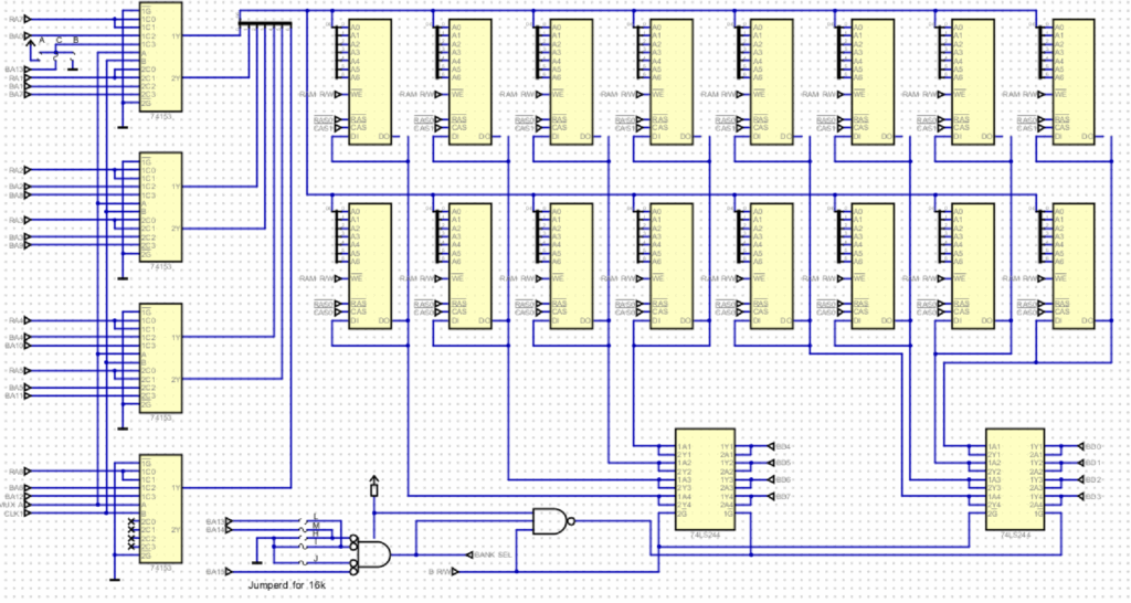
To follow the repairs I looked at the PET schematics – but got the wrong schematics. In the video they repair an original PET with static memory, not the dynamic memory used in my schematic.
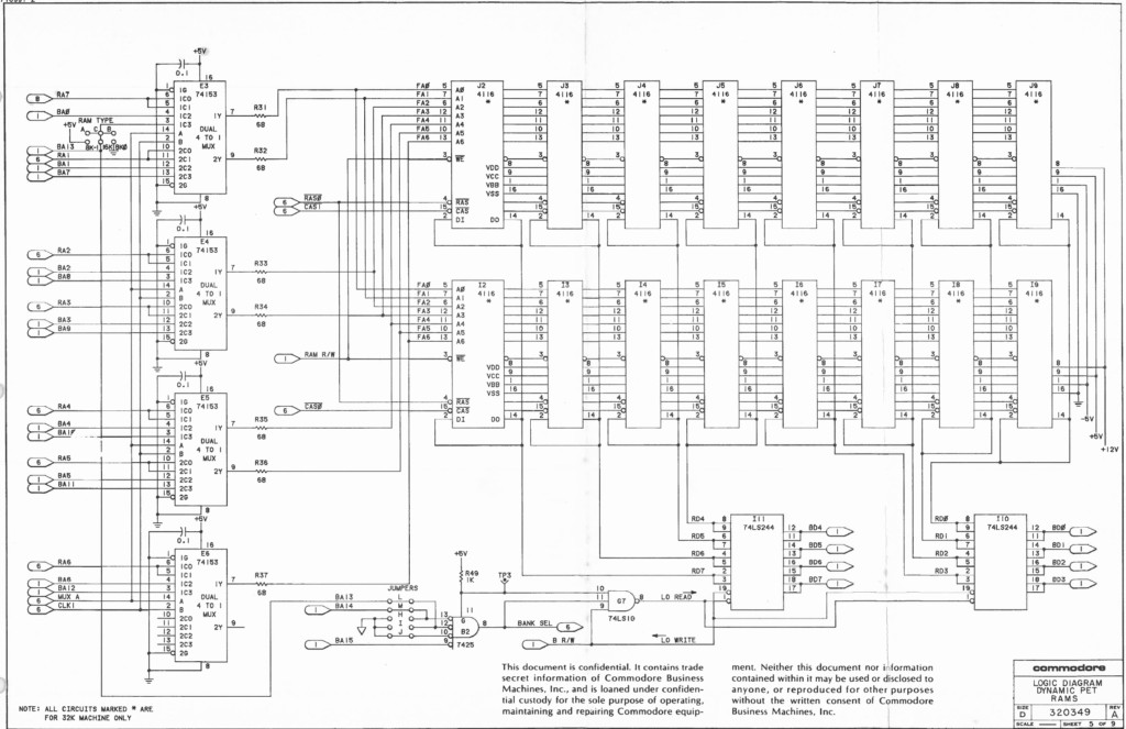
But as I have always been curious about how dynamic RAM works, especially the refresh part, I decided to simulate the memory part to see how it works.
This was done with the Digital Circuit Simulator by Helmut Neemann, which can be downloaded here.
Once the memory with its refresh cycles was running in the simulator I was intrigued by the video circuit. Having started in computing with the VIC20, I have been fascinated by how video was generated with just logic chips before the advent of dedicated video chips.
After the video circuit was working and generating a valid image the decision was made to just implement the whole system and see if it could boot.
Which it can 😊
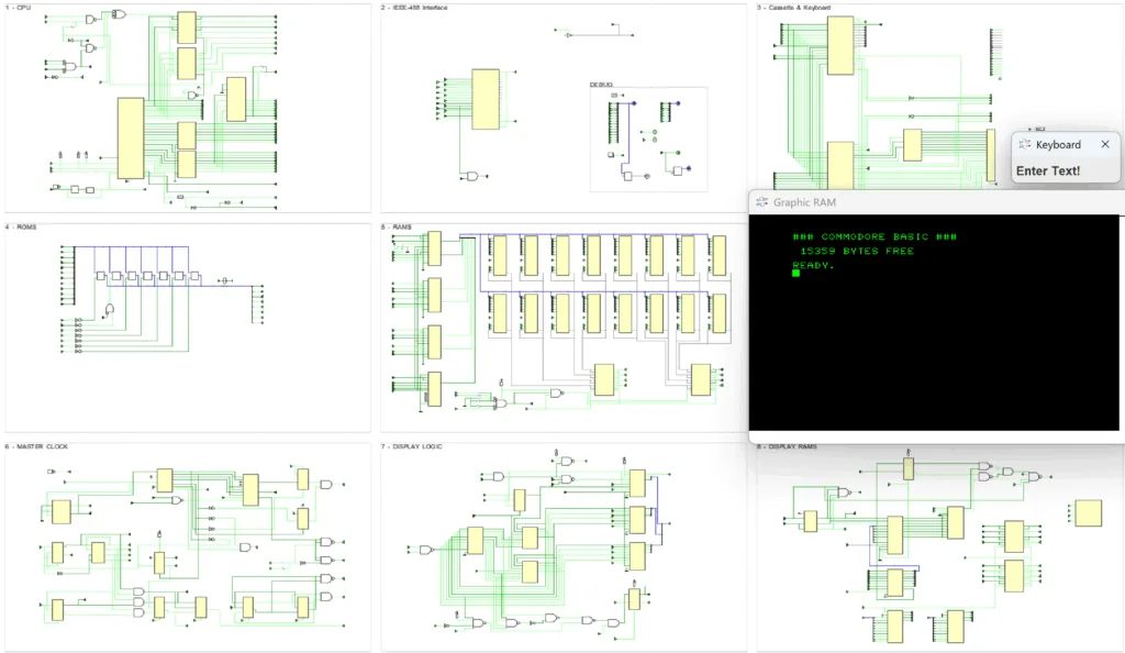
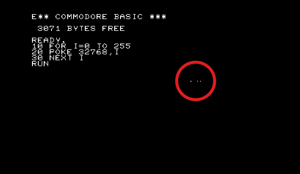
On the screenshot above you can see that all pages of the original schematic have been recreated 1:1 (almost)
After publishing this simulation I was asked by a user if I could also do a simulation for the “original” PET, the one with just static RAM as originally sold by Commodore in 1977. With the 6502 and the other special ICs already taken care of this was not too much of a problem:
Download & Starting the Simulator
All required files for the PET Simulator can be downloaded from Github.
- Unpack the zip file.
The zip file contains a plugin for the Digital Simulator that needs to be applied first. - Start Digital, go to ‘Edit’ -> ‘Settings’ -> ‘Advanced’ -> ‘Java Library’ and select the PETComponentsDigitalPlugin.jar file from the location where you unpacked the files.
- Restart Digital
- Open either the Mainboard-CBM3032.dig or Mainboard-PET2001-4.dig file
Now the simulation can be started by clicking on the  Button in the toolbar.
Once started, a window for the screen output and a keyboard input box pop up to interact with the system.
Caveat: If you cannot find the keyboard input box, it is probably hidden behind the screen output window.
The speed of the simulation is controlled by the 16MHz clock component in the DEBUG frame. Note: on the PET2001-4 Simulation this is a 8MHz clock.

A right click opens a dialog box where the simulated speed can be selected.
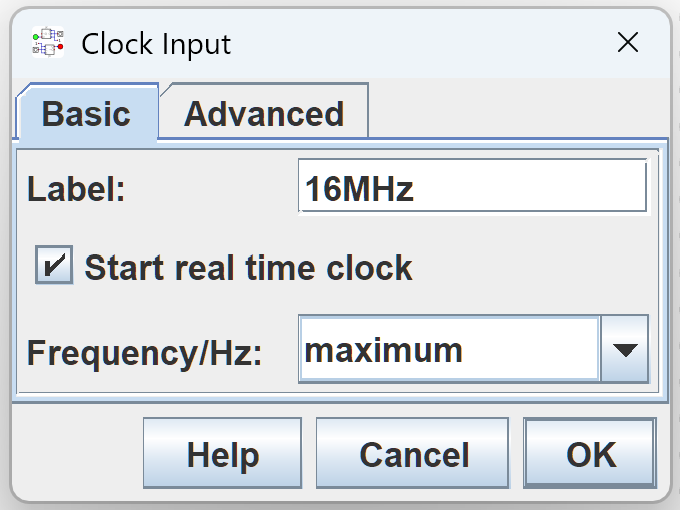
Please note, that this is the (simulated) speed of the nominal 16 MHz quartz crystal of the original PET. The 6502 CPU runs at just 1/16th of this clock (nominal 1MHz).
Deselect the `Start real time clock` checkmark to step through the simulation cycle-by-cycle by repeatedly clicking on the clock component.
In this mode it is also possible to set breakpoints on signals and run the simulation until a breakpoint is hit.
Further information on how to use the Digital Simulator can be found in its documentation (`HELP`->`Documentation`)
PET Versions
This project (currently) simulates two versions of the PET computer:
PET2001-32N / CBM3032
Also known as the “dynamic PET”, in Europe this version was sold as the CBM3032.
This version was chosen because, unlike the original PET, it uses dynamic RAM and, unlike the later 4000 and 8000 Series, the video output is generated only with conventional 74-series logic chips and not with a boring dedicated video controller chip.
This PET version runs BASIC V2, the version the system was originally delivered with.
While it should be possible to use BASIC 4 ROMs, the BASIC 2 has the nice Microsoft Easter Egg and any of the newer BASIC 4 commands (like DLOAD etc.) are of no use in this simulator.
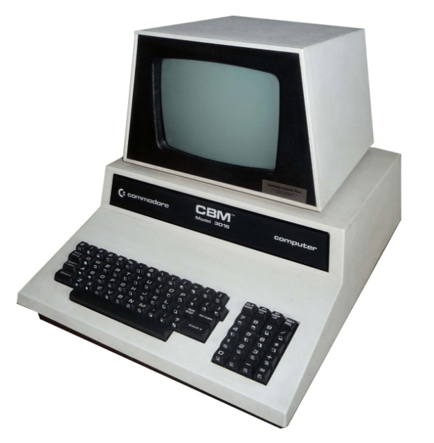
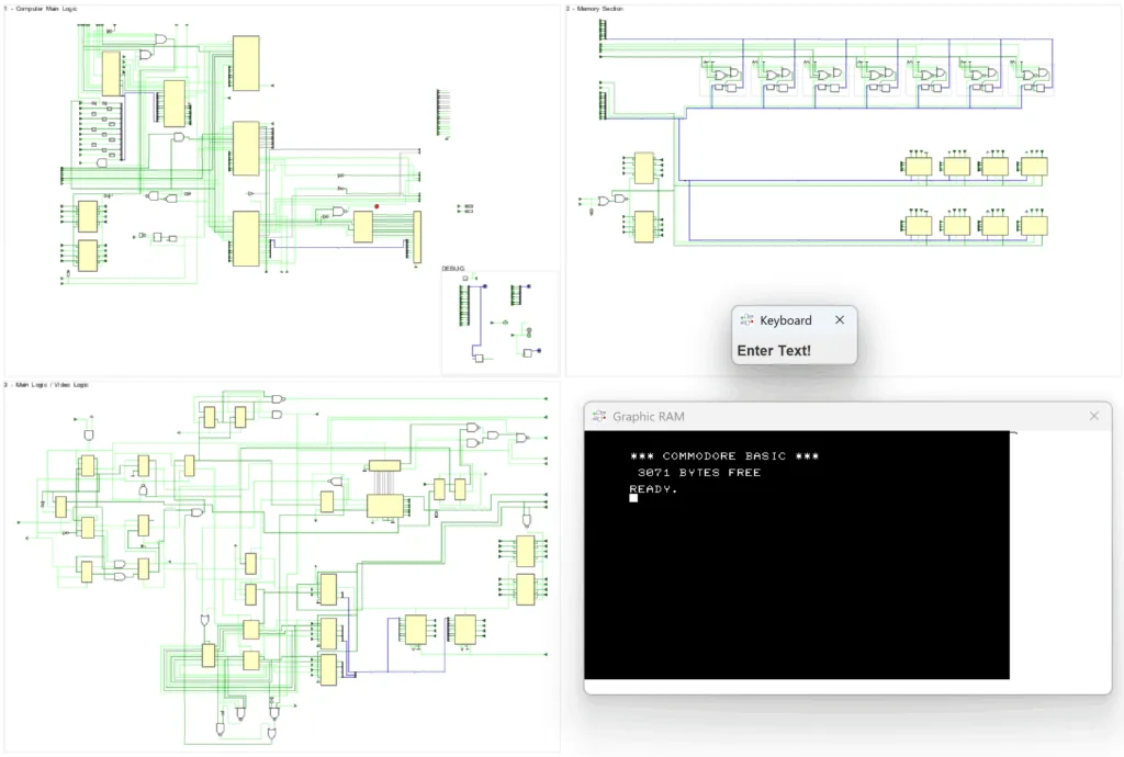
PET2001-4
also known as the “original PET” (with the chiclet Keyboard)
This version was added to the simulation because it is often the target of restoration projects. It is simpler in design (though with horrible schematics) and due to the 8MHz clock the simulation runs twice as fast.
The RAM is currently limited to just 4k which cuts boot time by almost a half and should be enough for most experiments. If required more RAM could be added easily.
It has BASIC 1 with all its quirks and bugs.
Speed
This PET2001N/CBM3032 simulation has currently about 580 logic elements, whose state needs to be calculated multiple times for every change of the main clock signal (a 16 MHz clock) as the signals propagate through them.
Additionally there are the screen updates which happen multiple times a second.
In other words this simulation is slow and far from running in realtime.
On my development machine (with a 2019 vintage Core i7-8565U @ 1.80 GHz) the simulation runs at about 200 kHz (200.000 cycles of the 16MHz clock per second) resulting in about 1.25% or 1/80th of the original speed.
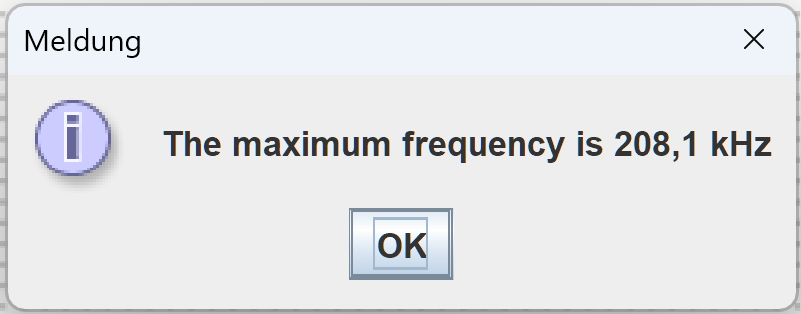
So trying to run anything on the simulated PET requires quite a bit of patience. Even getting to the BASIC ready prompt takes about 2 minutes.
The speed could be improved a bit by dropping schematics accuracy and replacing components with faster substitutes – e.g. replacing the 16 RAM chips with a single RAM simulation. But the goal of this simulation is schematic accuracy, not speed 😊
The PET2001 simulation runs faster because it only has to simulate 8 system clock cycles for every CPU clock cycle. Also with fewer RAM to check the system gets much faster to the BASIC ready prompt.
Compatibility
The simulated systems are fairly compatible with their real counterparts.
PET2001N/CBM3032
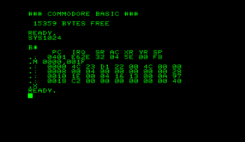
It can run the TIM (Terminal Interface Monitor) by executing SYS 1024
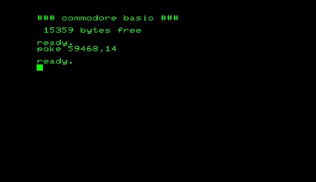
It can change to the lowercase character set with POKE 59468,14
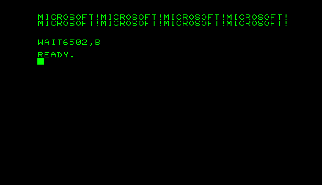
And it contains the Microsoft easter egg 😁
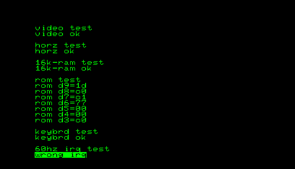
But it runs only part of the official Commodore Diagnostic Software and has a bug generating the correct 60Hz IRQ signal.
Original PET2001
The simulation of the original PET is also fairly accurate. It even shows the video sparkles when the CPU accesses the screen RAM
Which are very visible during the boot when clearing the screen memory (lots of quick screen memory accesses by the CPU)

Also the included BASIC V1 has the “PEEK Protection” of the BASIC ROMs, a feeble attempt of Microsoft to protect their IP.
Bugs
The simulation has some known bugs:
- Connecting the DO (Data Output) pins of the upper 16k RAM bank to corresponding pins of the lower bank causes spurious short circuits which will stop the simulation. The problem probably lies somewhere within the simulated RAM logic. This is currently fixed by disconnecting the DO pins of the upper bank from the system. On the plus side, this reduces boot time by about 2 minutes as the system RAM check only takes half as long.
- The IEEE-488 Interface is not implemented. While this could be added reasonably easy, some kind of simulated IEEE-488 device would be required to make the effort worthwhile. And that part is definitely non-trivial.
- PET2001N/CBM3032:The official Commodore Diagnostic ROM fails when testing the 60Hz IRQ, even though the IRQ signal is present.
- PET2001: The Diagnostic ROM fails during the VIDEO TEST.
What can you do with it?
Well, you can use this as a “Blinkenlights” thing and just admire all the signals wiggling millions of times just for a single blink of the cursor.
This simulation can also be used to follow the schematics and see how the different parts of the system interact with each other – not just on paper but with real state changes.
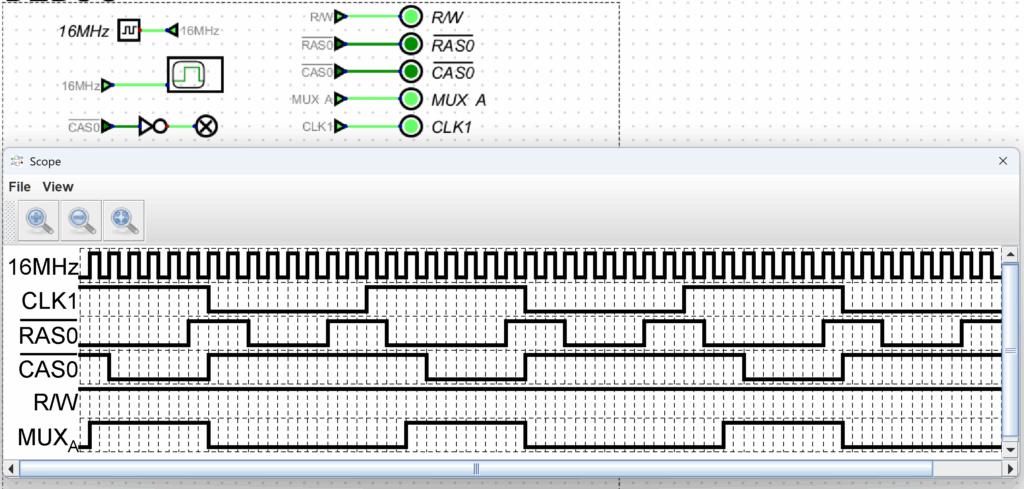
Digital has a output component called “Triggered Data Graph”, which is just a plain logic analyzer. Each time it is triggered, all ![]() Output Components with a name are sampled and shown on the scope display.
Output Components with a name are sampled and shown on the scope display.
For example, the screenshot below shows the ROW and COLUMN strobes for the RAMs in relation to the main system clock (CLK1)
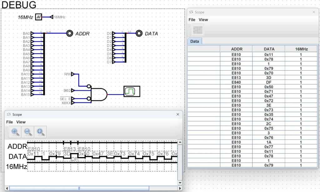
It is also easy to generate really complex trigger conditions with just a few circuit elements.
Here all writes to any I/O chips are logged to debug what the Diagnostic ROM is doing
This could be really helpful in debugging a real PET by looking at the simulated signals and comparing them to the signals of the device under test.
Future
For now I have spend enough time on the PET Simulator and will put my attention on other projects.
Time permitting I plan to come back to the simulator at some point to fix the bugs and maybe write some articles with an in-depth view at some components system and how and why it was implemented as it is.
Also, the video output circuitry of the original Apple 1 is quite intriguing and methinks a simulation could help to fully understand how it works 😉
Conclusion
If you have any thoughts on this project please leave a comment, either here or on the Github project Discussion page. If you do find more bugs – or even better – have fixes for the existing bugs, feel free to open an Issue.
Leave a Reply